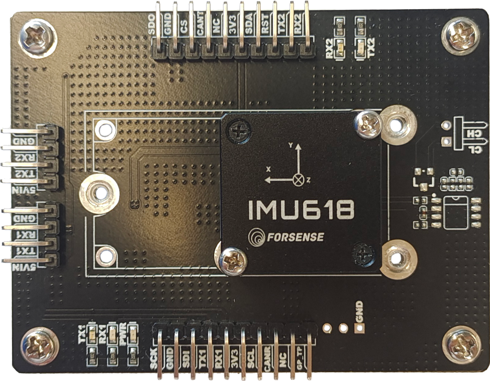
In order to facilitate the use of IMU618 series products (IMU618, IMU618-C, IMU618-T, IMU618-H IMU6132, etc.) by customers, a special test chassis has been developed, through which the IMU618 module can be connected to a PC to provide hardware support for testing, validation, and performance optimisation of customers' IMU (Inertial Measurement Unit) products. The test board has the following functions and features:
1. A variety of expansion interfaces:
the test board provides a variety of interfaces with the IMU618 module, including: USB, serial, CAN, TTL, I²C, etc., which is convenient for you to quickly connect the board to the computer and other control terminals. Meet a variety of test needs.
2. High-precision data acquisition:
the test baseboard can accurately capture the output data of the IMU sensor through the precision data acquisition circuit and high-speed sampling rate to ensure the accuracy and reliability of the test results.
3. Connecting with test host computer:
The test board and the host computer software enable you to easily carry out the configuration and control of various test parameters, including sampling rate, acceleration, attitude angle, gyroscope zero-deviation stability test, and so on.
4. Data recording and analysis:
the test board supports data recording and storage functions, you can save the original data during the test in the local storage device, which is convenient for customers to carry out subsequent offline analysis and evaluation.
Through the use of our test chassis, comprehensive IMU product testing and verification can be carried out on the computer, including sensor accuracy, zero bias, temperature effects, dynamic response and other aspects of the evaluation. In addition, the test chassis can also be used to optimise performance and adjust algorithmic parameters to improve product performance and stability. Our test chassis provide customers with a convenient and reliable solution to make the testing and optimisation of IMU products more efficient and accurate. We will provide a detailed user guide to ensure that customers can make full use of the functionality of the test bench for rapid testing and evaluation.
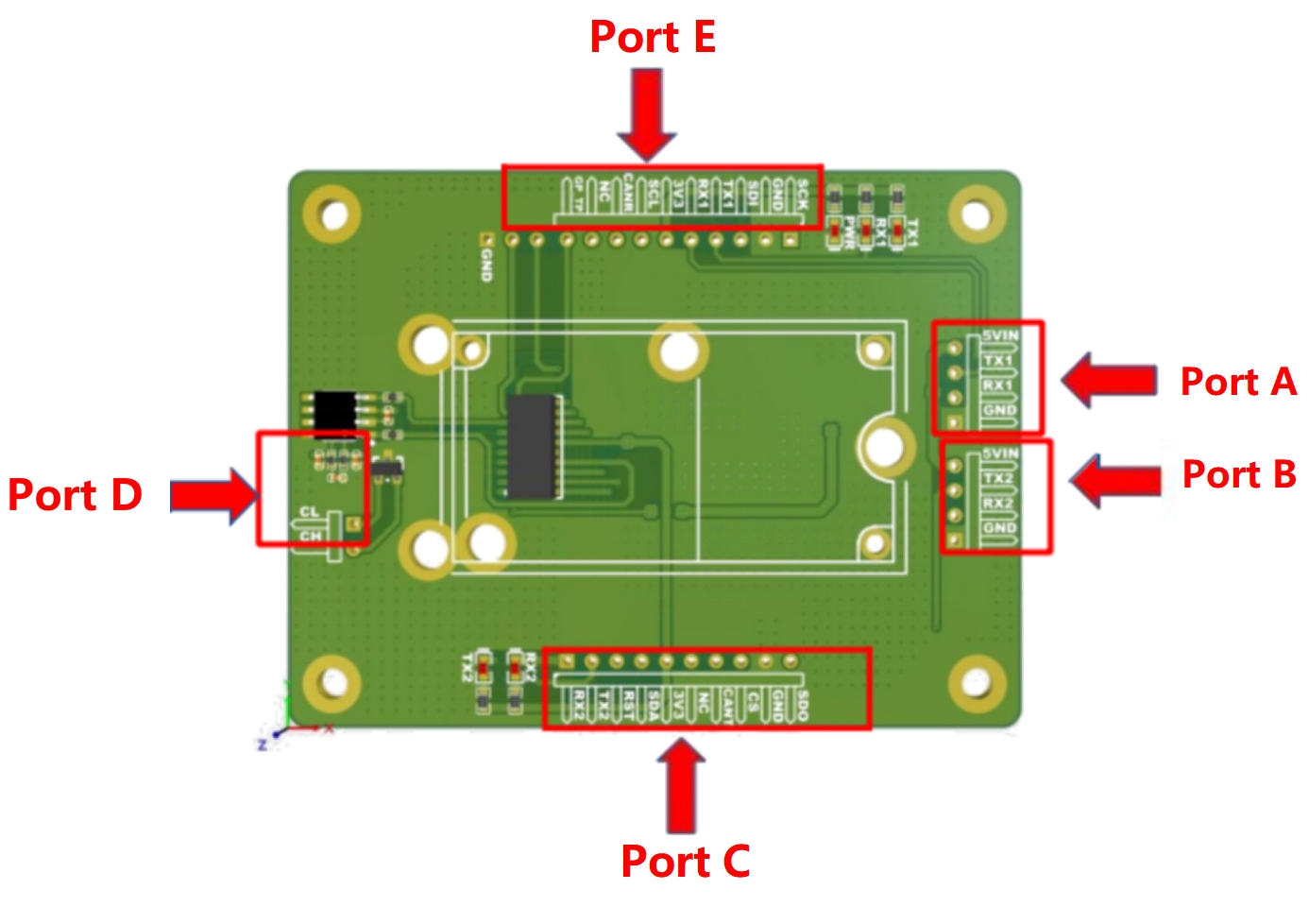
1. Interface A:
l Interface type: Serial (TTL to USB).
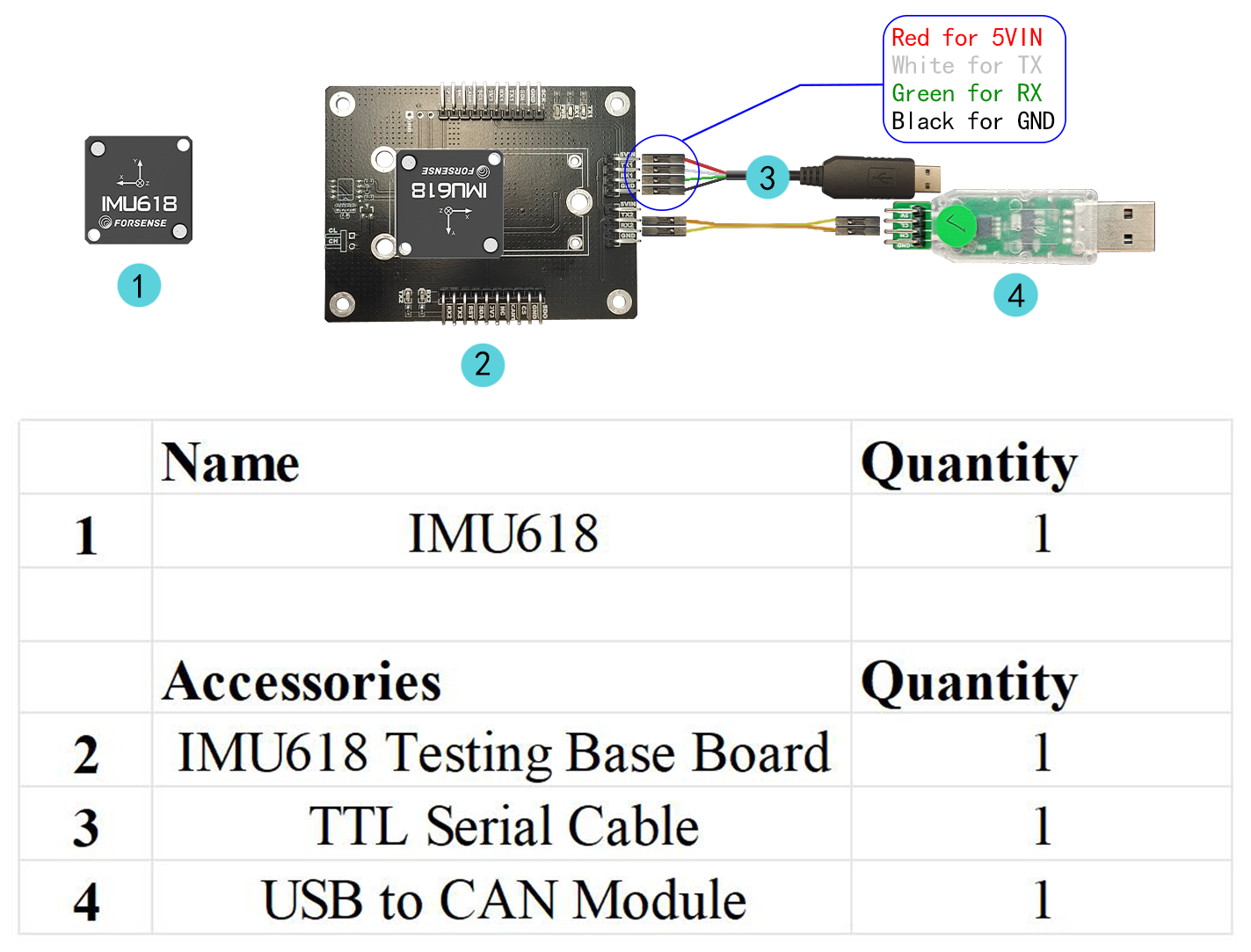
l This interface internally connects to IMU serial port 1 and can be used to connect to the host computer and read IMU data.
l Supply voltage: 5V
| 5V | 5 Volt power input |
| RX1 | Serial port 1 Receive, IMU datacom port (LVTTL) |
| TX1 | Serial port 1 transmit, IMU datacom port (LVTTL) |
| GND | Power Ground |
2. Interface B:
l Interface type: Serial (TTL to USB).
l This interface internally connects to IMU serial port 2 and can be used to connect to the host computer and read IMU data.
l Supply voltage: 5V.
| 5V | 5 Volt power input |
| RX2 | Serial port 2 Receive, IMU datacom port (LVTTL) |
| TX2 | Serial port 2 transmit, IMU datacom port (LVTTL) |
| GND | Power Ground |
3. Interface C:
| SDO | SPI Serial Data Output |
| GND | Power Ground |
| CS | I²C Serial Data |
| CANT | CAN port input, suspended when not connected |
| NC | Not Connected |
| 3V3 | 3.3V Power Input |
| SDA | I²C Serial Data |
| RST | External hardware reset input, internal pull-up (for SPI mode) |
| TX2 | Serial Port 2 Transmit |
| RX2 | Serial Port 2 Receive |
4. Interface D:
| CAN_H | CAN_H |
| CAN_L |
5. Interface E:
| SCK | SPI Serial Clock |
| GND | Power Ground |
| SDI | SPI Serial Data Input |
| TX1 | Serial port 1 transmit, IMU datacom port (LVTTL) |
| RX1 | Serial port 1 Receive, IMU datacom port (LVTTL) |
| 3V3 | 3.3V Power Input |
| SCL | I²C Serial Clock |
| CANR | CAN port receive, hang when not connected |
| NC | Not Connected |
| GP_TP | External Synchronised Sample Trigger Signal; Available for Data Ready(when connected to RTK second pulse pin) |
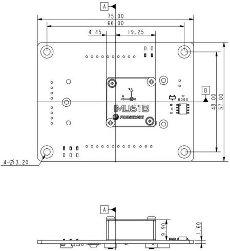
Dimension:
♦ Product classification
♦ Contact Us
| Telephone: | 86-13482465596 |
| E-MAIL : | yang_fan@bourdeaubros.com |
| Position : | Room 4F,Building 16,No. 1000 JinhaiRoad, City of Elite,,Pudong New Area,Shanghai |
 |  |  | |